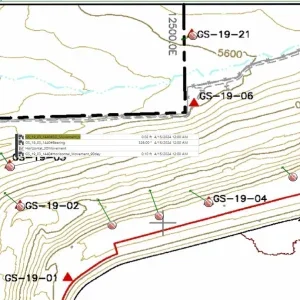
Located in Sichuan Province in Southwest China, Jinping II hydro project is the largest project on the Yalong river. The scheme – scheduled to be commissioned in December 2012 – has been designed to divert the tailwater of the upstream Jinping I hydro station through four headrace tunnels, making use of the water head along the 150km ‘Jinping Big River Bend’. The four tunnels have an average length of 16.7km, with excavation diameters raining from 12.4m to 13m. After lining, the inner diameter at the tunnels is approximately 11.8m, with the distance between the center of each tunnel designed to 60m. The tunnels are oriented in the direction N76°W from the intake, and N58°W at the end. The intake is sited at Jinfeng Bridge in the West of the tunnel, with the underground powerhouse located at Dashuigou in the East (Figure 1). Two access tunnels and a drainage tunnel run parallel to the headrace tunnels on the south side.
Geological conditions
The four headrace tunnels are excavated through the Jinping Mountain with overburden mostly above 1500m to a maximum of about 2525m. The rock consists of mainly massive blocky marble with minor sandstone slate and chlorite schist. The rock is integrated and mostly fresh. Orientation of the tunnel axis was designed to take large angles to the strike of the rock masses and major fault zones. Major parts of the rock along the tunnel are classified as II (29.1%) and III (53.6%) according to Chinese Standards on rock classification. The rest belongs to weak rock classified as Class IV to V. The Class II and Class III in the Chinese Standards roughly correspond to a Q system value of 10~40 and 1~10, respectively, or RMR value of 61~80, 41~60.
The rock formation provides relatively good conditions for excavation. The uniaxial compressive strength of saturated rock samples ranges from 50MPa to 85MPa, with the deformation modulus about 8 to 16GPa. The surrounding rock masses have good self-stability after tunnel excavation.
There are, however, two issues which present a challenge to tunnel construction. Firstly, there is a possibility that a large high pressure inflow may gush into the tunnel during the excavation work. The underground water is a type of fissure water connected by cast channel nets – and it has a continuous supply of sources. Secondly, rock bursts can occur as a result of the high in-situ stress caused by high overburden. The maximum major principal stress is estimated above 60MPa in the tunnel rock. Severe rock bursts have actually been encountered during excavation of the access tunnels and an adit, and thus modest to extremely intensive rock bursts are expected during construction of the headrace tunnels (Jiang and Wang, 2002).
Design of the headrace tunnels
The East side of Tunnels 1# and 3# will be excavated by a tunnel boring machine (TBM), thus the cross section is circular. All other tunnel sections will be excavated by drill & blast in a horseshoe shape. Sections excavated with TBM and drill & blast methods are shown in Figure 2.
Headrace tunnels 2# and 4# and sections of headrace tunnel 1# and 3# excavated by drill & blast will have an excavation diameter of 13m. The TBM excavated tunnel sections will have a diameter of 12.4m. The final tunnel will have a diameter of 11.8m after lining.
The rock support has been designed based on the rock mass classification. For rock masses of Class I and II, the surrounding rock masses are generally stable after excavation, meaning random rock bolts are applied. For rock masses of Class III, systematic rock bolts about 4.5m to 6m long and steel fibre reinforced shotcrete will be installed as permanent rock supports. For rock masses of Class IV and V –the entrance of the west and east sides of all the tunnels, the middle portion of the tunnels with rock mass classified IV, and in locations with modest to intensive rock burst (classified as rock burst Class IIIb, IVb, Vb) – concrete (C25) lining up to 70cm thick will be installed as a permanent rock support, in addition to temporary rock support with systematic rockbolts and reinforced shotcrete. The total length of this work is about 8.65km for all the tunnels.
Grouting will be carried out along the tunnel to reinforce the surrounding rock masses. To improve the hydraulic condition of the tunnels, thinner concrete (C25) lining up to 40cm thickness will be applied to rock masses Class II and III (Hehai Report, 2003, Wu et al., 2005).
Tunnel construction
TBM and drill & blast methods – For faster excavation, all four tunnels are divided into west and east sections, meaning there are two tunnel faces to excavate. The east portions of tunnels 1# and 3# will be excavated by two 12.4m diameter TBMs. The west portions of these tunnels, and the full length of tunnels 2# and 4#, will be excavated using the drill & blast method. Tunnels 1# and 2# formed one bid package assigned to one contractor, with tunnels 3# and 4# assigned to another contractor. At the time of writing, the TBM machines in both tunnels 1# and 3# are assembled and will soon start to bore.
Measures to handle the underground water – During excavation of the headrace tunnels, the contractor has to be prepared for the potential of high pressure, large water inflow. After sealing an adit, the inflow was measured with pressure as high as 10.22MPa. During excavation of the adit and the access tunnels, the maximum water inflow is about 4.9m3/sec~7.3m3/sec. The high-pressure water inflow caused difficulties for excavation. It can lead to instability of the surrounding rock masses and too great risk to safety of the crews. There are four approaches to handle the potential high-pressure large inflow – probe, drain, control and seal. Details of these approaches are:
• Probing involves investigating the geological conditions in front of the tunnel face through various forecast measures before excavation. This will not only probe potential water inflow but also help ensure safe excavation. Excavation must occur through the underground water bearing zone for faster tunnelling progress.
• Draining involves diverting a large water inflow from the work site through a special drainage channel, such as the drainage tunnel.
• The control approach makes it easier to either stop inflow or to allow the water in. This is a necessary preparation to handle the inflow. If control is lost, it will be time consuming to seal a large inflow – causing construction delays. This system should be organized as soon as possible after bypassing a large water inflow.
• It is also important to seal the water inflow when it is not needed, to allow drainage of the underground water at the inflow locations.
Ventilation – For the east tunnels, there are several connections between tunnels 1# and 2#, and between tunnels 3# and 4#, meaning there are two sets of parallel tunnels. This forms a ventilation network where the ‘one tunnel in – one tunnel out’ approach is applied. Ventilation will be provided by fans placed in the tunnel. The ‘blow out by one duct’ concept is adapted with a certain length of duct to each tunnel face.
In the west portions of tunnels 1# and 2#, tunnel 2# is the main transportation tunnel during the construction period, while tunnel 4# is the main transportation for the west portions of tunnels 3# and 4#. There are several connection tunnels among the four headrace tunnels for drainage purposes. The length of the west portions of all four tunnels is 4200m, which will be excavated by drill & blast using truck transportation. Based on current international experience, it is feasible to use a single 4000m long duct to provide ventilation to each tunnel face. It may require compressors with large capacity and high quality duct, however it provides a flexible solution to the changing conditions expected in the tunnels.
Rock bursts – The high in-situ stress along the headrace tunnel can cause rock bursts during excavation. Measured maximum major principal stress is approximately 42.11MPa vertical, indicating that gravity stress dominates. It is estimated that the major and minor principal stresses could reach 63MPa and 26MPa respectively at the location of the headrace tunnel with maximum overburden. Measures to prevent from rock bursts during excavation are:
• Use of a TBM: The east side of headrace tunnels 1# and 3# will be excavated by TBM to a total length of about 21km. It is believed that the boring excavation will reduce the disturbance to surrounding rock masses, thus reducing the probability of the occurrence of the rock burst. TBM tunnelling can also increase safety of crews should there be a rock burst during excavation.
• Reinforcement of the surrounding rock masses: a) shotcrete or steel fibre reinforced shotcrete applied immediately after the excavation, b) pattern rockbolts to prevent the loss of rock blocks and slabs; and c) wire mesh or steel ribs.
• Optimization of the blasting process: In light to modest rock burst sections, smooth face blasting should replace normal blasting. In intensive rock burst sections, a combination of smooth face blasting and pre-fissure blasting should be used.
• Use of stress release drilling to reduce the energy in the rock masses (Wu 2007, Norconsult Reports No 2 and No 3, 2004).
Conclusion
Construction of the Jinping headrace tunnels presents many challenges, including the complicated hydrogeological and geological conditions, high overburden, large cross section of the tunnels, and the tunnel length. This paper introduced some key design and construction aspects with a focus on the potential difficulties caused by large underground water inflow and rock bursts which may be encountered during tunnelling. Based on experience gained during construction of the Jinping access tunnels and information gained during geological explorations, some preliminary measures to handle these difficulties have been presented. As tunnelling progresses, more problems and difficulties may arise and efforts will be needed to ensure safe and efficient construction.
Wu, Shiyong, Ph.D., Professorial Senior Engineer, Deputy General Manager, Ertan Hydropower Development Company Ltd, No 288 Shuanglin Road, Chengdu,?Sichuan,?China 610051, email: wushiyong@ehdc.com.cn; and Huang, Ziping, Ph.D., Senior Engineer, Norconsult AS, Vestfjordgaten 4, 1338 Sandvika, Norway, email: ziping.huang@norconsult.no


