The analysis of the stresses and deformations in a highly statically indeterminate arch dam was a challenging task for structural engineers in the past when the analyses had to be performed without the benefit of today’s electronic tools. Therefore, simplified methods were developed, such as the trial load method based on the beam theory. Most of the existing arch dams built before the 1980s were analysed using this method. In this method, the arch dam is modelled by a series of cantilever beams and arches, which are interconnected at their intersections. The elastic supports of the cantilevers and arches were represented by different types of foundation springs, which were derived from half space solutions. The resulting three-dimensional (3D) structural system would be a beam model. The number of cantilevers and arches in such models was generally kept small in order to minimise the computational effort. Besides the computational effort, the main advantage of beam models is that the stresses vary linearly across the sections of the cantilevers and arches due to the assumption of plane sections. This also includes the contact between the cantilevers and arches with the foundation rock. Because of its simplicity and the fact that the behaviour of beam models can be easily understood by the dam engineers, the trial load method has survived almost up to now. The arch dam analysts still refer to cantilever and arch stresses, although such a distinction is less meaningful today when an arch dam is analysed using 3D solid elements.
When the dam body is rigidly connected to the foundation rock, then stress singularities occur at the upstream heel and the downstream toe of the dam under the assumption of the linear-elastic behaviour of mass concrete and rock [3]. These stresses are infinite if there is a sharp corner at the heel or toe of the dam. In many FE analyses of arch dams, relatively coarse models are used and stresses are often calculated only at integration points of finite elements. Thus, the real nature of the stress concentration along the edges may not show up in the results of the stress analyses [4].
High tensile stresses occur mainly at the upstream heel due to the water load exerted by the reservoir, leading to crack formation. However, as the bond between the dam body and the rock foundation is not perfect, and since the rock may be jointed or may undergo inelastic deformations under high local stresses, these cracks are usually not detected, and they may have no effect on the safety of the dam. This applies mainly to cracks in massive arch dams with a base width of several tens of meters. In slender dams, cracking is a much more severe problem, as they may reduce the shear resistance and thus may propagate further due to the high shear forces at the base of the cantilevers. Crack propagation is also enhanced by water pressure in the cracks, as it reduces the effective stress and thus the shear strength of the cracked section.
Although high tensile stresses are mainly observed at the upstream heel of the dam under the usual load combinations, high dynamic tensile stresses may also occur at the downstream toe under seismic actions. In view of the fact that the tensile strength is less than 10% of the compressive strength of mass concrete (a similar ratio may be assumed for the foundation rock), the emphasis of the subsequent discussion is on the zone of high tensile stresses at the upstream heel of the dam. As soon as a tension crack develops in the dam or the foundation, water will penetrate into the crack. Therefore, the wet crack at the upstream heel will propagate further than a dry crack at the downstream toe of the dam.
The objective of this paper is to analyse and discuss the stress concentration at the upstream heel of a large arch dam. For that purpose, the load combination comprising the gravity load acting on the dam and the water load due to the reservoir are considered. The effects of the properties of the foundation rock (elasticity, joints, anisotropy) as well as the contact between mass concrete and rock are discussed.
Based on a linear-elastic FE analysis, it can be expected that cracks exist at the upstream heel of very large arch dams. Such cracks – if they exist – can only be observed when the reservoir is empty or by exploratory drilling in the highly stressed zone. Because of the silt at the bottom of the reservoir, the cracks are usually not visible.
The problem of high tensile stresses at the upstream heel of large arch dams is well known and in some cases, such as the Katse dam in Lesotho, the tensile stresses are controlled by a special joint with variable pressure according to the reservoir level.
The best known and oldest solution is the peripheral joint or the so-called ‘Pulvino’, which was first developed by Italian dam engineers. It should be mentioned that Enguri arch dam in Georgia, the highest arch dam in the world, also has a peripheral joint. However, the great majority of arch dams do not have any foundation joints at all.
Overview of numerical analyses
The following types of analyses were carried out for a 250m high arch dam:
•3D linear-elastic analysis of dam-foundation system assuming that the dam and the foundation are perfectly bonded. This is the standard analysis for arch dams. The results of this analysis were then used to determine the load sharing between the arch and cantilever actions.
•3D nonlinear analysis of dam-foundation system assuming that no tensile stresses can be transferred at the dam-foundation contact; hence, a crack will form under tension. Two conditions of the dam-foundation interface were considered: (a) without uplift pressure (dry joint), and (b) with uplift pressure (wet joint; hydrostatic pressure was varied linearly from the maximum value at upstream heel to zero at downstream toe).
•Equivalent 2D analysis of crown cantilever of an arch dam by determining the water pressure acting on the cantilever in such a way that the radial displacements obtained from a linear-elastic analysis of the 2D crown cantilever are the same as those of the 3D arch dam (Note: this approach is basically the same as that of the trial load method). The following cases were investigated using the equivalent 2D model: (i) Linear-elastic behaviour of mass concrete and foundation rock (isotropic properties): investigation of the effect of mesh size at upstream heel and downstream toe of the dam; parameter study by varying the modulus of elasticity (E) of the foundation rock (ratio of E-modulus of concrete to that of rock: 0.5, 1.0, 2.0 and 5.0, for each of which the equivalent water load acting on the 2D cantilever was determined separately); (ii) Linear-elastic behaviour of mass concrete and foundation rock (orthotropic material properties of rock): investigation of the effect of the orientation of the joint systems; (iii) Nonlinear analysis with no-tension contact elements at the dam-foundation contact: Two conditions of the dam-foundation interface were considered: (a) without uplift pressure (dry joint), and (b) with uplift pressure (wet joint; hydrostatic pressure was varied linearly from the maximum value at upstream heel to zero at downstream toe); (iv) Embedded dam with perfect bond between mass concrete and foundation rock; linear-elastic behaviour of mass concrete and foundation rock (isotropic properties): variation of embedment from 5m to 10m; (v) Nonlinear material behaviour of concrete and rock with biaxial strength properties based on the Kupfer model [2] of concrete available in ADINA [1]: parameter studies with the following values of tensile strength of both concrete and rock: 1.0, 0.5 and 0.1 MPa.
The stresses were computed in all cases for the load combination comprising the dead load of the dam and the full water load. The dam displacements were calculated only for the water load. The dead load was applied in one step; incremental construction of the dam and the grouting sequence of the contraction joints were not simulated.
In the nonlinear analyses, the gravity load was applied first, followed by the water load. The sequence of the load application is important in nonlinear analyses. In the nonlinear concrete model with a tensile strength of 0.1 MPa, a large number of iterations were required to achieve convergence. The error tolerance was defined in terms of a global energy criterion with a tolerance value of 0.1%.
In the 3D arch dam and 2D cantilever models with no-tension contact elements at the dam-rock interface, the tolerance of the contact forces was specified as 2%.
Numerous checking analyses were needed for the verification of the reliability of the results of the nonlinear analyses. In comparison to the linear-elastic analyses, the nonlinear analyses are very time-consuming and need a lot of experience.
The 3D arch dam-foundation model and the equivalent 2D model of the crown cantilever are shown in Figure 1. The main advantage of an equivalent 2D model is that a very fine mesh can be used to perform parameter studies very efficiently. In the 3D arch dam models, usually a relatively coarse mesh is used and local effects such as those discussed in this paper cannot be analysed efficiently.
Material properties
For the 3D arch dam analysis, mass concrete and rock were assumed to be homogeneous and linear-elastic materials. The modulus of elasticity of mass concrete was taken as 33 GPa and that of the foundation rock as 24 GPa. The Poisson’s ratios of mass concrete and rock were taken as 0.20 and 0.25, respectively. The mass density of the concrete was chosen as 2500kg/m3 and no gravity load was applied on the foundation rock.
For the 2D cantilever analyses, the same elastic properties of the mass concrete were taken as for the 3D analysis. However, the E-modulus of the rock was varied from 6.6 to 66 GPa in the sensitivity analyses in which isotropic linear-elastic material behaviour was assumed.
The analyses with orthotropic behaviour of the rock foundation were performed for joint orientations of 0°, 45°, 90° and 135°. The E-moduli in the tangential and vertical directions of the joints were taken as 33GPa and 6.6GPa, respectively. The equivalent shear modulus was taken as the geometric mean of the shear moduli in the two orthogonal directions.
For the contact elements at the dam-foundation contact, a friction angle of 35° was assumed (friction coefficient: 0.7).
Most of the material parameters of the nonlinear Kupfer model of the mass concrete are those of the standard concrete model provided in the computer program ADINA. The most important parameter in this model is the tensile strength, as this quantity governs the formation of cracks. Concrete and rock were assumed to be homogeneous and isotropic materials.
Discussion of results
In Figure 2, the cracked zone of the dam-foundation contact in the 3D model is shown for the dry and wet conditions. It can be noted that the crack width at the base of the dam increases from 8m when the uplift pressure was not considered (dry joint) to 30m (about half of the base width) when the uplift pressure with a triangular distribution was applied at the dam-rock contact (wet joint).
In the subsequent figures, the results of the equivalent 2D crown cantilever model are shown.
Figure 3 shows the distribution of the vertical stresses along the base of the dam obtained from a linear-elastic analysis (dead load and equivalent water load according to Figure 1). The stress concentrations at the upstream heel and downstream toe are clearly visible. For that purpose, a very fine FE mesh as shown in Figure 7 was used.
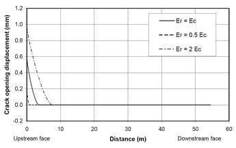
In Figure 4, the vertical stresses and the crack opening displacements at the dam-foundation contact are shown for the dry and wet joint conditions. The effect of the foundation stiffness on the crack width is shown. It can be clearly seen that a rigid foundation leads to a larger crack than a soft one. In the figure, the total stresses are plotted, i.e. the effective stresses would become zero when the vertical compressive stresses are less than 2.5MPa at the base of a 250m high dam.
In Figure 5, the effect of the crack opening at the dam-foundation contact on the stress distribution within the crown cantilever is shown. It can be seen that the maximum principal tensile stress reduces from 25MPa (at upstream heel) to 1MPa when a crack is allowed to form along the dam-foundation
contact. The largest compressive principal stress also reduces; however, the zone with high compressive stresses becomes bigger at the downstream toe of the dam.
In Figure 6, the shear stresses in the dam are shown for the following conditions: (i) dam bonded to foundation, (ii) dry joint at dam-foundation contact, and (iii) wet joint at dam-foundation contact.
Finally, the crack pattern that would develop at the base of the dam is shown in Figure 7, when the same ADINA concrete material model with a tensile strength of 0.5MPa is used for both the mass concrete and the foundation rock.
When tensile strengths of both the concrete and the rock are equal to 1MPa, 0.5MPa and 0.1MPa, cracks originating at the upstream heel of the dam and with depths of 15m, 19m and 21m, respectively, would develop in the foundation rock. The effect of water in the cracked zone is not taken into account. Therefore, if the water pressure would be included, the orientation and length of the crack may change. It is interesting to note that the crack extends into the foundation and does not propagate along the dam-foundation contact, provided that the bond between the dam and foundation remains intact. However, if the strength properties at the dam-foundation contact are much inferior to those of the parent mass concrete and rock (rock properties are usually improved by consolidation grouting), then the crack may develop along the dam base.
The results of the other parameters such as the orthotropic properties of the foundation rock and the embedment of the dam in the foundation are not presented in this paper in the form of figures.
In the case of the embedment of the dam in the foundation and a perfect bond between concrete and rock at the embedded faces of the dam, the stress concentration will occur at the location where the foundation surface intersects with the dam body, instead of the edges of the dam base.
For the orthotropic rock properties, the maximum principal stresses at the upstream heel of the dam are as follows for different inclinations of bedding planes or joint systems: 0°: -2.5MPa (compression); 45°: 13.1MPa; 90°: 26.2MPa; and 135°: 15.4MPa. At a distance of about 30m from the dam-foundation contact, the stresses within the crown cantilever do not depend on the properties of the foundation rock. However, the orthotropic rock properties have an important effect on the deformations of the dam.
Conclusions
The following conclusions may be drawn from the comprehensive numerical stress analysis of a 250m high arch dam subjected to dead load and water load:
•1 – At the upstream heel and the downstream toe of a concrete dam (reentrant corners), stress concentrations occur with theoretically ‘infinite’ elastic stresses, which may lead to cracks in the foundation rock, the concrete dam or along the dam-foundation contact.
•2 – For isotropic conditions, a crack originating from the upstream heel of the dam is likely to develop in the rock foundation.
•3 – A crack may develop along the dam-foundation contact when its strength properties are inferior to those of the mass concrete and the foundation rock.
•4 – The uplift pressure at the dam-foundation contact greatly increases the crack width; this is mainly a problem for very high dams (in the present study the maximum hydrostatic pressure reaches 2.5 MPa). For the formation of cracks, the effective stresses in a cracked section are relevant.
•5 – The embedment of the dam in the foundation rock has only a minor effect on the stress concentration at the upstream face.
•6 – The maximum tensile stresses at the upstream heel become larger with increasing foundation stiffness.
•7 – The maximum crack sizes obtained from the different parameter studies are as follows: a) 3D arch dam model with dam-rock interface modelled by contact elements and with triangular distribution of uplift pressure at dam-foundation interface: crack width of up to 30m; b) 2D model of crown cantilever with dam-rock interface modelled by contact elements and with triangular distribution of uplift pressure at dam-foundation interface: crack width of 10 m for foundation rock half as stiff as dam concrete, and crack width of 28m for foundation rock two times stiffer than dam concrete; c) 2D model of crown cantilever with concrete material model having a tensile strength of 0.1MPa for both mass concrete and foundation rock (without the effect of water pressure in the crack): 21m deep crack in rock foundation
•8 – Cracking can be expected to occur at the upstream heel of a massive arch dam. These cracks are usually stable, as long as shear stresses do not exceed the shear strength of mass concrete and rock. Shear cracks are generally a problem for slender arch dams in wide valleys, where the cantilevers carry a substantial part of the water load. In narrow valleys, most of the water load is carried by arch action.
•9. – If the crack at the base of a dam opens, the deformations of the dam will increase resulting in a redistribution of the stresses, i.e. the arch action will attract more forces.
• 10 – The existence of cracks at the upstream heel of large arch dams can only be detected by exploratory boreholes or by the observation of changes of the seepage discharge when the foundation crack has damaged the grout curtain.
Author Info:
Dr Martin Wieland, Chairman, ICOLD Committee on Seismic Aspects of Dam Design, and Dr Sujan Malla, Poyry Energy Ltd., Hardturmstrasse 161, CH-8037 Zurich, Switzerland. Email: martin.wieland@poyry.com, sujan.malla@poyry.com


