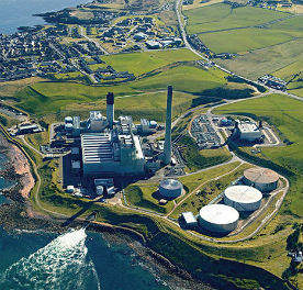
The agreement between Shell and the UK government takes the Peterhead carbon capture and storage project, which envisages installation of post-combustion amine capture on Scottish and Southern Energy’s Peterhead gas-fuelled combined cycle plant, to the next stage, front end engineering and design (FEED). The aim of this FEED phase, which is scheduled to start during Q2 2014, is to further develop design details and de-risk the project ahead of a final investment decision, which could be made in late 2015. Subject to positive final investment decisions by Shell and the UK government and the receipt of all relevant consents and permits, the installation is expected to be up and running by the end of the decade.
The project, which is located in northeast Scotland, is ultimately to develop the key CCS technologies and is one of two remaining in the CCS commercialisation competition being operated by the UK government, to which it says £1 billion has been committed to support construction of "up to two projects." The other project remaining in the running is the coal-plus-biomass fuelled White Rose oxyfuel project planned for the Drax site, which is also now in the FEED stage. A total of about £100 million is being invested in the two FEED studies, the government says.
If it goes ahead, Peterhead would represent the first industrial-scale application of CCS technology at a gas-fired power station anywhere in the world.
With the award of these development contracts, the reserve projects announced in March 2013, the Captain and Teesside projects, will now be deselected – although they may be able to re-enter at a later stage.
The UK government says it is continuing discussions with CCS developers outside of the competition ‘on what measures they may need to take their projects forward.’ This includes discussions with the Captain and Don Valley projects under what is known as the ‘FID Enabling route’, an interim arrangement enabling investors to proceed with low carbon projects in advance of the UK’s new contracts-for-difference funding scheme coming fully into effect.
”The signing of this agreement is a hugely important step towards the UK’s delivering the world’s first CCS demonstration facility on a gas-fired power station" said Ed Daniels, chairman of Shell UK. "CCS could be critical to reducing carbon emissions at a time of growing global demand for energy. The successful demonstration … would be a step towards proving its commercial viability as a tool for mitigating climate change. It could also help diversify the North Sea oil and gas industry and so contribute to the sector’s long-term commercial health."
“SSE is proud to be working with Shell on proposals to install this cutting-edge technology at our Peterhead plant," said Paul Smith, managing director, Generation, SSE. "CCS could play a major role in ensuring secure, low carbon energy in the future and we are pleased to be playing our part in its development"
The Peterhead project
The project, led by Shell with strategic support from SSE, aims to capture 10 million tonnes of CO2 over 10 years. Natural gas is a relatively clean burning fossil fuel, but Shell aims to make it cleaner, capturing up to 90% of CO2 emissions generated. The compressed gas would be sent via pipeline for disposal in Shell’s depleted Goldeneye gas reservoir in the North Sea. SSE would be responsible for power plant modifications, while Shell, which owns the Cansolv capture technology, would be responsible for installing the CCS equipment.
The existing plant consists of three 277 MWe SGT5-4000F (V94.3A at the time of installation) Siemens gas turbines in CCGT mode with three Doosan Babcock heat recovery steam generators providing steam to one of the turbines inherited from its time as an oil fired plant. One of these 277 MW units will be a retrofitted with the Cansolv absorption system, a technology based on post-combustion capture that uses amines to absorb the CO2, a method that has been used by the industry for around 50 years. It is therefore a mature and cost-effective solution. It has already been demonstrated as feasible, having been demonstrated in several small installations in the USA and it is recognised as the best available technology for post-combustion CO2 capture.
The Peterhead CCS project is particularly well-placed to progress, as a significant proportion of the infrastructure needed is already in place. The power station provides a large existing source of CO2 emissions. It lies close to available offshore pipelines that can safely transport the CO2 to the depleted Goldeneye gas reservoir, some 100km from shore. The CO2 would then be safely stored more than 2.5km beneath the North Sea.
Transport and storage
Following feasibility studies on a variety of options, Shell’s proposal is to build a short length of new pipeline from Peterhead power station and link this into the existing offshore pipeline from St Fergus to the Goldeneye reservoir.
CO2 will be stored in the depleted Goldeneye reservoir, which lies about 100 km from the shore in the outer Moray Firth, and 2.5 km beneath the seabed. The reservoir has the key geological features necessary for storing CO2 permanently – a body of high-quality porous rock overlaid by impermeable rock to seal the CO2 in place.
Goldeneye was a producing gas field from 2004 to 2011. Injection is the reverse of production – during production, natural gas was drawn from the rock and naturally replaced by salt water; injection of CO2 will drive the salt water back out of the store and into the adjacent rock formations from where it came. The Goldeneye gas store will be monitored throughout its life.
Onshore FEED
One contract has already been awarded, to Technip, the Paris based infrastructure specialist working mainly in the oil and gas industries, which has won the contract from Shell UK to provide FEED for the onshore elements of the project.
Technip’s operating centre in Milton Keynes, UK, which executed a pre-FEED study for the Peterhead CCS project about 18 months ago, will execute the FEED for this next phase. This office serves as a centre of excellence for the development of CCS end-to-end solutions. Technip’s record in clean technologies includes the world’s first floating offshore wind unit and the world’s largest biofuels unit. Technip has widened its range of services in the downstream business since it acquired the process technologies specialist Stone & Webster from Shaw Group in 2012.
The Cansolv process
Shell’s Cansolv’s technology is said to be highly adaptable to a wide variety of industrial applications, gas flow rates and carbon dioxide concentrations, and has been installed in other major CCS projects supported by Shell, including the Quest oil sands project in Alberta, Canada, the SaskPower Boundary Dam facility in Saskatchewan and the Gorgon project in Australia.
The Boundary Dam capture plant, which is undergoing commissioning, provided a good reference for the design process of painstaking FEED, and de-risking evaluation followed by scale-up to commercial dimensions. The 150 MW unit is a lignite fired plant with emissions of 12% CO2 and 1000 ppmv of SO2. The specified capture target was 90%. Many lessons were learned during the CAD process and in lab-scale verifications, in particular about the most effective absorber geometry, materials and corrosion, and chimney design. At the end of the trial period the facility is expected to be capturing CO2 and saleable SO2 in acid form at the rate of 1 000 000 tons/year and 60 tons/day respectively.
The pure carbon dioxide product output is suitable for enhanced oil recovery (EOR).
The Cansolv system employs a regenerable solvent and utilises a proprietary amine technology which captures the CO2 from the flue gas and releases it as a pure stream. An advantage of post-combustion capture is that carbon dioxide removal from the flue gas is segregated from the production facility.
The system is essentially standalone and, therefore well suited to retrofit.
Its benefits are said to be lower regeneration energy and superior kinetics compared to conventional amine solutions, high loading capacity combined with ease of regeneration, improved resistance to oxidative and thermal degradation, and advanced solvent and technology development.
The key process steps (Figure 2) are:
- Feed gas is quenched and saturated in a circulated water pre-scrubber.
- Gas contacts the lean amine solution in a counter current mass-transfer packed absorption column.
- CO2 is absorbed and the treated gas exits to atmosphere.
- Midway through the column, partially loaded amine is removed from the tower, cooled and reintroduced over a layer
- of mass transfer packing.
- CO2-rich amine from the absorption column is pumped through a lean-rich amine heat exchanger and then on to the regeneration column.
- Rising, low-pressure saturated steam in the column regenerates the lean amine solution. Carbon dioxide is recovered as a pure, water saturated product.
- Lean amine is pumped from the stripper reboiler to the absorption column for reuse in capturing CO2.
- The carbon dioxide is directed to by-product management systems.


